Parts used


| Quantity | Part Number | Link to part |
| 2no | 007 | Land Rover Defender chassis to seatbelt bracket |
| 3no | 061 | Land Rover Defender 90/110/130 & Series SWB/LWB Underfloor Support Strutt |
| 3no | 087 option A | Land Rover Defender 90/Series SWB Rear Floor Support Top Hat |
| 1no | 103A | Land Rover Defender 90 & Series SWB Rear Tub Floor |
| 6no | 319 | Rear Tub Body Lower Rubber Mountings Spacer Pads – LR Defender & Series |
| 1no | 334 | Land Rover Defender Fuel Tube Support Bracket |
| 1 pair | 395C | Stepped Wheel Arch Repair – LR Defender 90 |
| 250no | 1001 | Type A Rivets Grip Range 1.6mm – 6.2mm |
| 50no | 1002 | Type B Rivets Grip Range 4.8mm – 11mm |
| 150no | 1003 | Type C Rivet Countersunk Grip Range 4mm – 6mm (Ali Body/Stainless Stalk) 4.8 x 10 |
| 10m | 1903 | 100mm x 1mm Single Sided Foam Tape |
Tools used
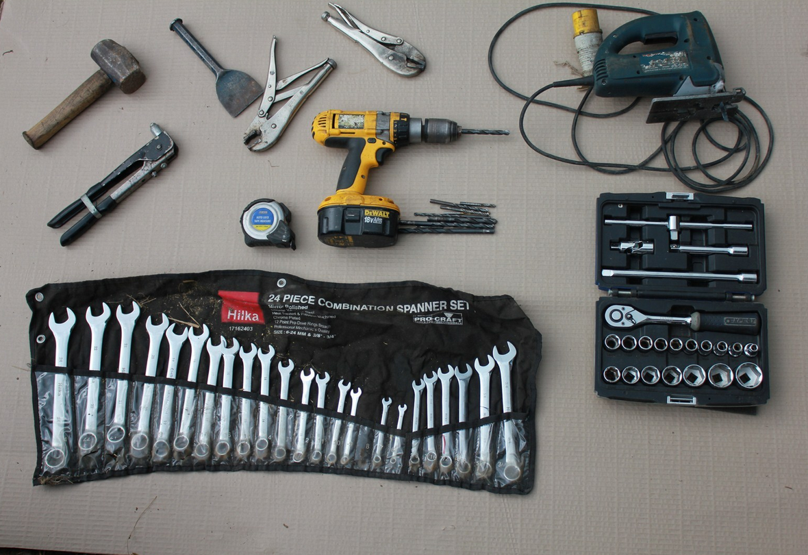 |
Selection of spanners and sockets set Pry bars Screwdriver set Countersink drill bit Riveter Drill and various drill bits Tape measure and Marker Hammer and bolster chisel Appropriate PPE, Goggles, Gloves, Boots |
Steps
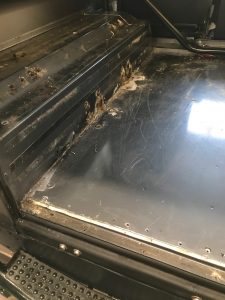
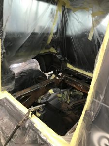
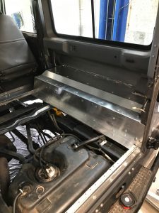
1 |
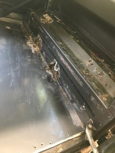
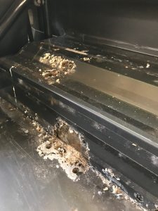
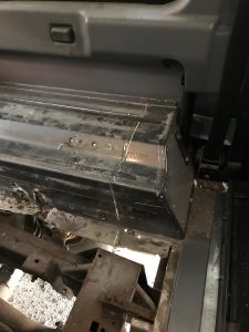
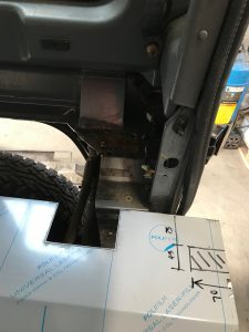
The rear tub prior to any work commencing.
Inner wheels arches have corroded due to sub frame on the underside to hold the rear forward facing seats. |
   |
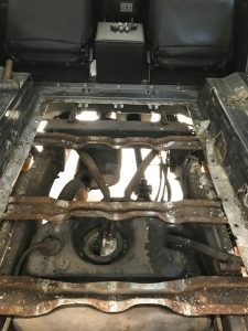
2 |
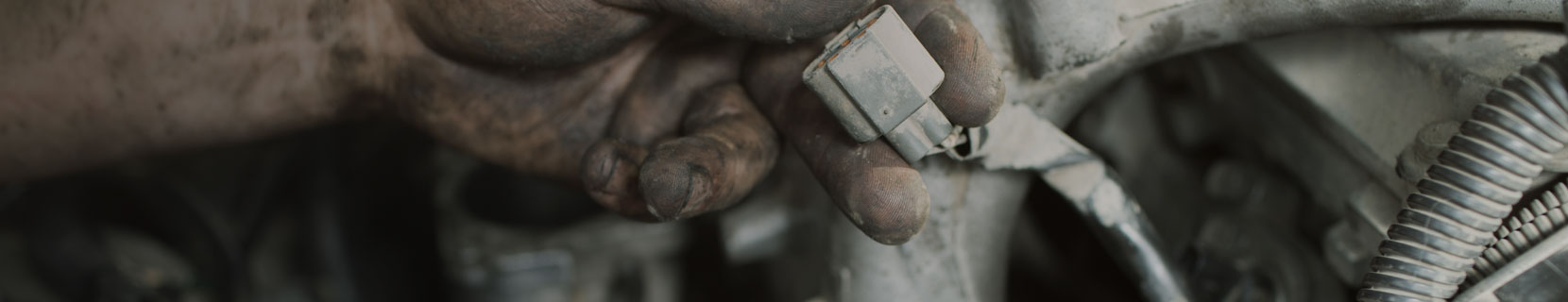
Drill out the spot welds, as first image, to be able to remove the floor (when drilling out these, take care not to go too deep and drill through the fuel tank.)
Drill rivets out of the rear floor support and the front of rear tub to be able to remove the top hats. Use a pry bar to remove the rivets that attach the underfloor supports to the wheel arch. |
   |
3 |
Under the arch, measure 50mm around the sub frame (YRM289) and then transfer these measurements to the inside of the vehicle, where it will be easier to cut. To ensure the seats ago back in the same position, take datum points so the sub frame goes back in the same location.
We cut using a jigsaw and once the perimeter has been cut, remove the wheel arches and sub frame. |
   |
4 |
Get the new wheel arches and mark up each side for the wiring harnesses (for speaker pods and lights). These measurements will be dependent on your vehicle.
Whilst we had access to the chassis, we changed the ‘fuel tube support bracket (YRM334)’ & seat belt to chassis brackets (YRM007) for our own galvanised one, by simply unbolting the original. |
   |
5 |
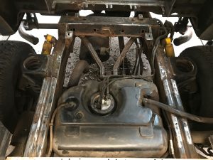
As we have access to the chassis, we decided to remove the fuel tank to be able to provide better coverage for undersealing. We also replaced the fuel tank cradle (YRM118) with our own, to make access easier for future repairs. Please see workshop 18.
Prior to undersealing we used a grinder to remove excess rust to bring it back to bare metal on the chassis. We masked off the rest of the car, for protection prior to undersealing. |
   |
6 |
We applied our 1mm thick foam tape (YRM1903) on the entire sub frame to provide a barrier between the two dissimilar metals. We then cross referenced the new arch against the original arch and riveted the sub frame on. Once in place, we seam sealed around the perimeter, to prevent water ingress.
The we slotted the new wheel arch and sub frame into place by riveting and sealing onto the existing wheel arch (where 50mm should have been left around the perimeter). |
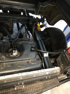   |
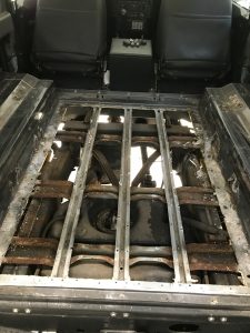
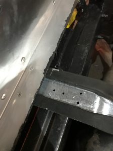
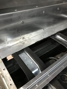
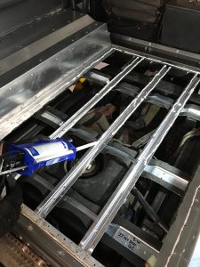
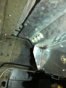
7 |
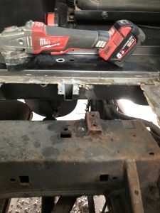
As shown in first image, we added affixed some foam tape on top of the ‘fuel tube support bracket’ as it comes into contact with the floor.
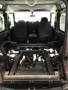
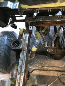
1903 foam tape was used along the edges of the underfloor supports (YRM061), to help create a barrier between two dissimilar metals. We riveted the underfloor support strutts into place, using CSK rivets (YRM1003). As this will allow the new floor to sit flush against the wheel arches. See 3rd image for reference. |
 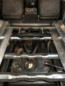  |
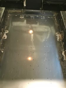
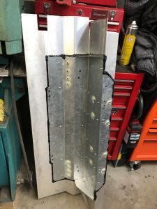
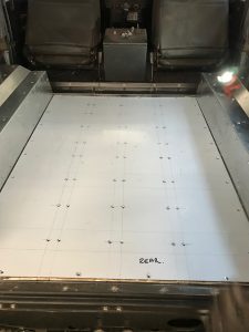
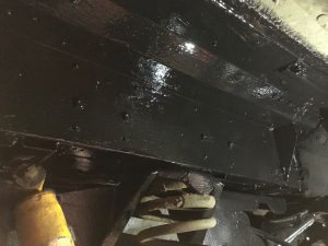
8 |
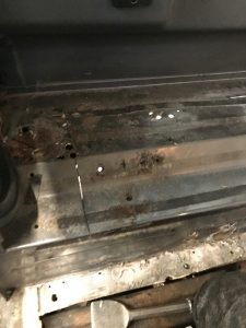
Then we riveted the top hats using 1001 rivets, making sure they went through the supports and top hats.
We used 1003 (counter sunk) rivets around the perimeter to help ensure that the floor will fit flush. As 2nd image, you can see the sealant, which was placed under the wheel arch to help provide a barrier. |
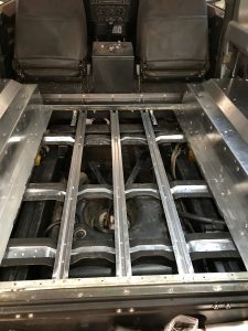  |
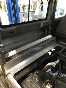
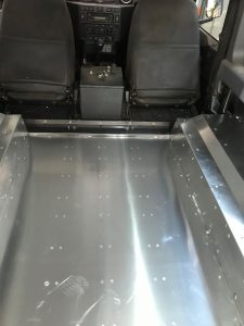
9 |
Prior to putting the floor in, we used permanent marker to mark each edge of the top hats against the rear floor support as well as marking each edge of the underfloor supports against the wheel arch. Using a straight edge, we drew the outline for the top hats and the underfloor supports, based on the marks made.
We then riveted the floor into place in all 4 corners. This secured the floor, we then matched drill the top hats (YRM087) and floor (YRM103) whilst avoiding the fuel tank, using a CSK bit to accommodate CSK rivets We then removed floor (YRM103). This allowed us to apply sealant along the length of the top hats and around the perimeter. We then installed the floor, inserting rivets (YRM1003) making sure all holes lined prior to riveting If you use counter sunk rivets, you can remove the protective film after riveting, if using another rivet, please remove this before. |
   |
| 10 | We applied sealant to the overlap joint on underside of wheel arches to prevent water ingress.
We then applied an underseller to the underside of wheel arch Finally, remove the protective seal on the floor and reattach the door.
If you’re doing this for a Series, it’s the same process. The main difference would be, that you wouldn’t have the sub frame . |
   |
This worked was carried out by Glenn Crawford & Steve Watson.