Parts used
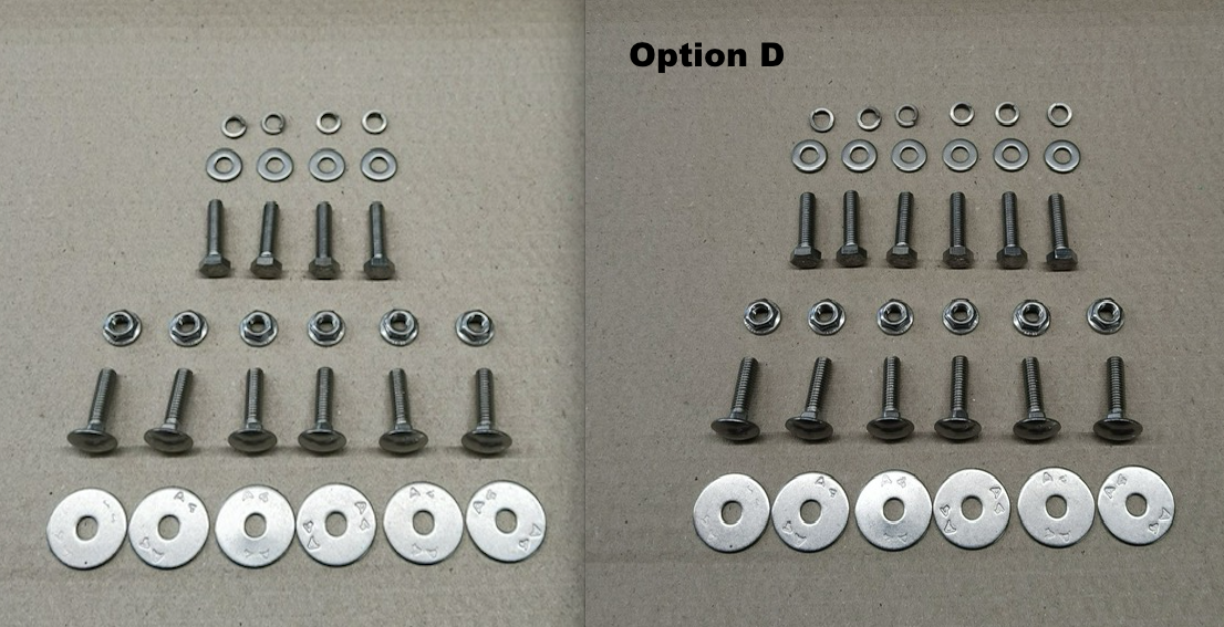
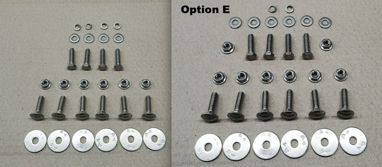
S/S Front Mudflap Bracket Fixing Kit – LR Defender
|
YRM Ref |
YRM 1132 |
|
JLR/OEM Ref |
|
|
Description |
S/S Mudflap Bracket Fixing Kit – LR Defender |
|
Fits |
1983 – 2016 Defender |
|
Thickness/Material |
Stainless Steel Fixings |
|
Finish |
Self Finish |
|
Extra Information |
JLR/OEM numbers used for reference only |
|
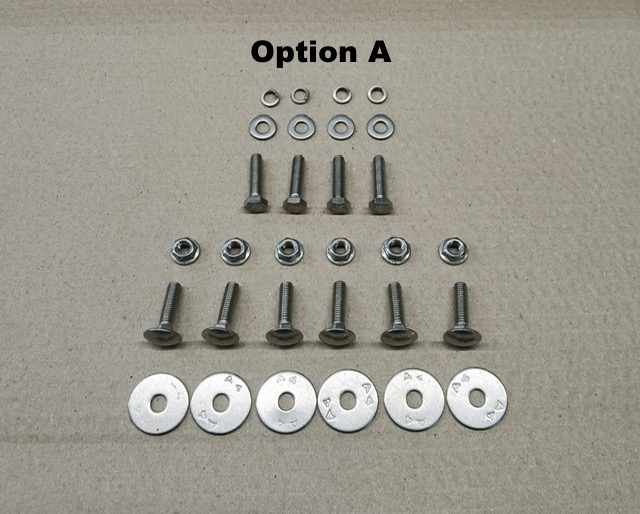
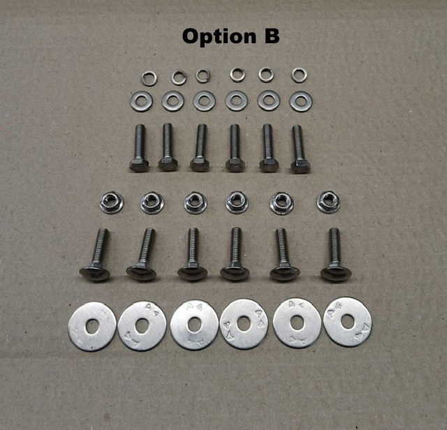
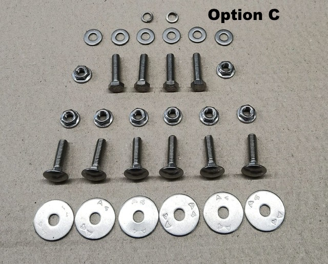
Fixings Included |
Please note – A4-80 is the equivalent of 8.8 high tensile bolts |
|
Workshop |
Excl. VAT £3.50 - £6.50
Incl. VAT £4.00 - £8.00

Related Products
-
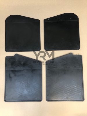
Mud Flaps pre Td5 – LR Defender 90
Excl. VAT £10.00 - £40.00
Incl. VAT £12.00 - £48.00 Add to -
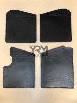
Mud Flaps – LR Defender 90 Td5 & Puma
Excl. VAT £10.00 - £40.00
Incl. VAT £12.00 - £48.00 Add to -
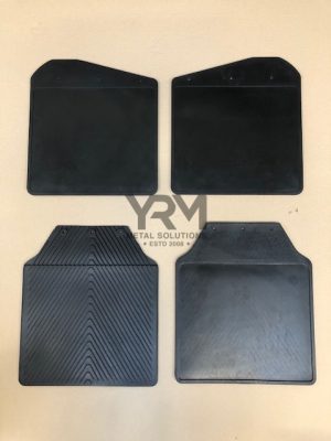
Mud Flaps – LR Defender 110/130
Excl. VAT £10.00 - £40.00
Incl. VAT £12.00 - £48.00 Add to -
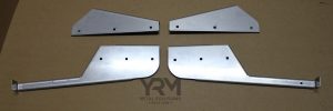
S/S Front or Rear Mudflap Brackets – LR Defender 110/130 (83-16)
Excl. VAT £32.20 - £85.95
Incl. VAT £39.00 - £103.00 Add to -
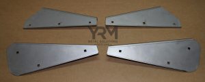
S/S Front or Rear Mudflap Brackets – LR Defender 90 (83-16)
Excl. VAT £32.20 - £61.95
Incl. VAT £39.00 - £74.00 Add to
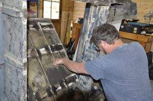
Steve Miller shows how to repair a corroded rear tub using basic tools and some perfectly-made repair sections
When we think about corrosion in Land Rovers, our minds often jump straight to the chassis, quickly followed by the bulkhead – the well documented areas of the rust. The thing is, these areas all have one thing in common – they’re made of steel and, over time, exposed to steel without any protective coating will rust.
It’s often said that Land Rovers don’t rust, because they’re made of aluminium. This, as a lot of owners of Series, early Ninetys and One Tens (and early Defenders) will know, is an urban myth. Its not uncommon to slightly dubious areas of paintwork and, on closer inspection, you may see a slight white powdery substance forming. This galvanic corrosion is often found when two dissimilar metals touch over a period of time. Steel and aluminium are the two main metals used to manufacture of our beloved vehicles. When Land Rover originally designed these cars, little consideration was given to the effects of galvanic corrosion. Basically steel wins, and eats the aluminium for breakfast.
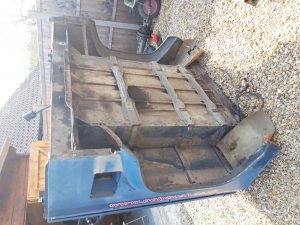
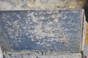
Take the rear tub of my 1985 Ninety, for example. Looking from the underneath the tub, I could see the three underfloor struts running left to right (I had these replaced a few years ago), and these sit across the aluminium so-called top hat sections that run front to back. Together, these sections that run to back. Together, these sections form the load bay structure. Over time, the steel underfloor support struts have eaten into the aluminium.
These supports are fairly straightforward to replace. However, replacement of the three aluminium top hat sections running front to back is more involved. The issues occurred from manufacture, as no barrier was used between the conflicting metals. Once we replace these parts, and eliminate any future corrosion issues, well have a serviceable rear tub for many more years to come.
Steps
1 |
Making life easier
While its completely possible to undertake this work with the tub in situ, it’s a lot easier with it removed, especially as I have additional repairs to undertake |
 |
2 |
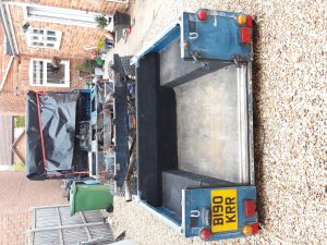
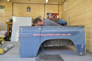
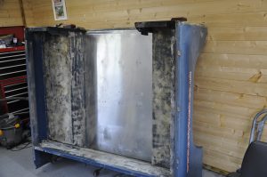
Working position
Initially, the best working position is with the tub stood on its rear end with some protection underneath it. Ensure it is completely stable before working. |
 |
3 |
Let’s make a start
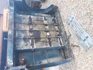
I started by unbolting the three under-floor support struts which where galvanised replacement . There were no rivets to drill connecting to the top hats. |
 |
4 |
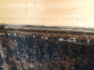
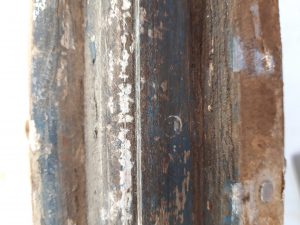
Dissimilar metals
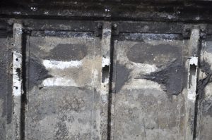
At all nine points where the steel struts touched the aluminium top hat they’ve been eaten . New parts from YRM Metal Solutions will replace these. |
 |
5 |
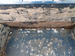
Theshold
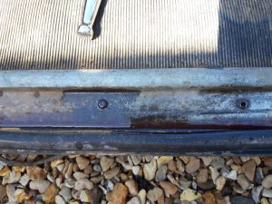
With the tub now correct way up, the rear threshold needs removing. Chances are, the screws need a good dose of WD40 to make undoing easier. |
 |
6 |
Exposed floor
With all floor coverings removed, the rivets and spot welds holding the floor panel down are exposed. I’ll be replacing the floor too, as its seen better days. |
 |
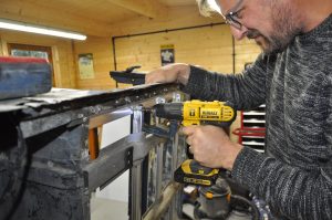
7 |
In the tub
Working my way around the edge, drilling the rivets with a 5mm drill bit. There were some steel rivets on the front that needed help from an angle grinder. |
 |
8 |
Lots of drilling
You’ll spend a fair bit of time drilling out rivets around the outer edge, and you can use a hammer and punch to knock them through |
 |
9 |
Found out
If you were keeping your original floor, you’d have to grind more carefully than this, but the floor is nearly ready to come out. |
 |
10 |
Making a hole
If the original floor is to be retained, then all the spot welds holding the top hats to the underside would also need drilling out. |
 |
11 |
Find the welds
To replace the rear floor support (YRM part 116), which is below the floor at the rear threshold position, use a wire brush to expose the spot welds for drilling. |
 |
12 |
More drilling
Your 5mm drill bit would have had quite a workout at this stage so it might be getting a little blunt. I used a couple on this project. |
 |
13 |
Hammer time
Once the spot welds are drilled, you’ll need to use hammer and bolster to help separate the floor support from the angled body mount. |
 |
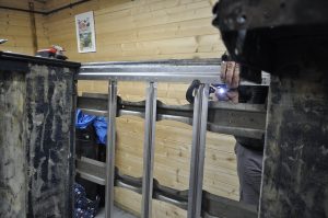
14 |
New metal
With the old floor loosely in place, I could line up the new rear floor support section and clamp it in place using clamps at both ends. |
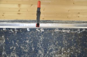 |
15 |
Match drilling
Before match drilling the old spot-welded holes, it’s worth noting where the holes go for the door threshold (previously removed) so you don’t clash with rivets. |
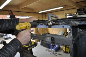 |
16 |
Squared up
I’d temporarily refitted the galvanised underfloor struts to straighten things up, though first I riveted the new rubber mounting spacers on by using this hand riveter. |
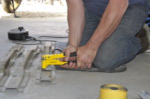 |
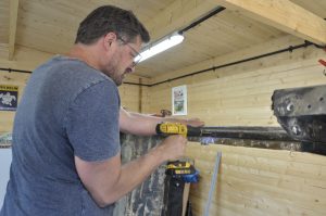
17 |
Hard work
The hand riveter was tough going and I realise that I needed to borrow a mate’s air riveter. That was far easier – there’s no going back now! |
 |
18 |
Making light work
An absolute doddle with the use of an air riveter. Here using Type C countersunk rivets to ensure the new floor will sit flush against the support section. |
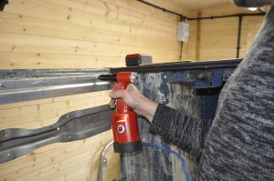 |
19 |
Coming together
With the three new top hats placed into position, ensuring that the joggled end sits underneath the rear floor support, its time to drill through. |
 |
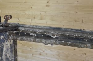
20 |
Completing the structure
Now they are riveted on from the tub side, as seen here. I also removed the bolts on the floor support members to match-drill through the new floor. |
 |
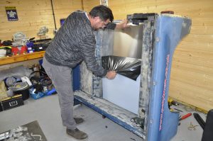
21 |
New floor panel
The beautiful mill-finish aluminium 2mm thick floor I snow laid in position and the protective coating peeled back – very satisfying. I won’t want to scratch it. |
 |
22 |
And finally
To secure the floor, a lot more drilling is required, match drilling from behind using the existing holes down the wheel arch edges, then riveting in place from the tub side. It’s worth making sure you drill and rivet as you go, rather than drill all the holes in one as you’ll find that each time a rivet goes in, it’ll pull up, and eventually your pre-drilled holes will no longer line up. Lastly, whenever steel touches aluminium, it’s worth bearing in mind that a gasket needs to be made up. Do this by purchasing a roll of sticky-sided foam tape from YRM (part no 1903/5m), or you can use PVC insulation tape. Simply cut to size and stick |
 |
Working with the tub on the truck
With the tub fitted to the vehicle, extra care must be taken when drilling. For example, Td5 Defenders have their fuel tank fitted underneath the floor at the back, so make sure you don’t drill into the top of your tank! Also, extra measurements and data points will need marking up because you won’t necessarily know where to match drill through into the top hats. Using a straight edge will help between the data points.
This workshop was carried out by Steve Miller and can be found in August 2020 copy of LRM